User Tools
This is an old revision of the document!
Table of Contents
Gen.Node v2.1-jD
This is jDrones version of the UC4H General-Purpose Node. Documentation is accurate only if you are using original jDrones Gen.Node boards.
Board Definitions
TOP Side of the UC4H Gen.Node v2.1-jD
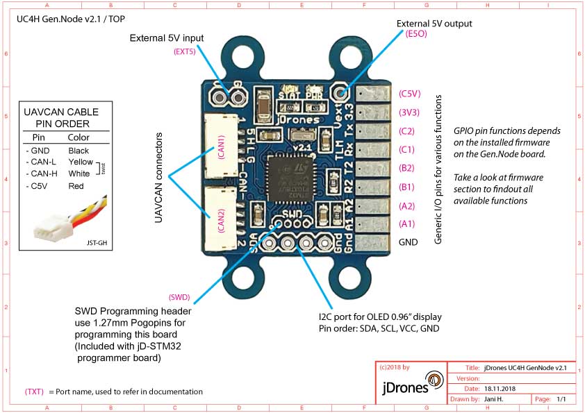
Connector Definitions
| Connector | Description |
|---|---|
| EXT5 | External 5V input if you need more power than what C5V line can provide |
| E5O | Output pin for EXT5 connector. Used for external 5V is needed |
| CAN1 | UAVCAN main connector. Identical to CAN2 port, can be used for linking to another UAVCAN device or terminator |
| CAN2 | UAVCAN main connector. Identical to CAN1 port, can be used for linking to another UAVCAN device or terminator |
| C5V | C5V is connected to CAN1/2 power line and protected with 500mA automatic FUSE. |
| 3V3 | 3.3V LDO regulated output pin. Same LDO provides power to the main MCU. Max output 3V3/300mA. |
| C2 | C2 / Tx1, |
| C1 | C1 / Rx1, |
| B2 | B2 / Tx2 / TLM, |
| B1 | B1 / Rx2, |
| A2 | A2 / SCL, |
| A1 | A1 / SDA, |
| GND | Common ground, used to ground your additional hardware |
Firmwares
There are two main softwares for this board. One is the bootloader and another is the operation firmware. Please do not mix them. The firmware you upload with the SLCAN board over the UAVCAN databus. The bootloader is uploaded via the SWD connector.
This board is coming with the latest UC4H Bootloader uploaded at jDrones. Normally you do not need to upload the bootloader unless you want to upgrade it or have “bricked” your UC4H board. You need a jDrones STM32 Programmer guide for burning the bootloader into this board.
You can always download the latest firmware and bootloader from our document site.
Firmwares/Bootloaders, please take a look at our firmware page
