User Tools
can:slcan
This is an old revision of the document!
Coming right up.
In meanwhile, please take a look at http://olliw.eu/2017/uavcan-for-hobbyists/
SLCAN Board
Board definition
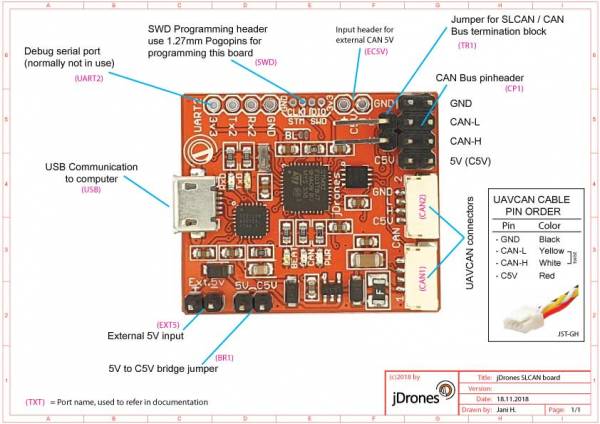
Picture of SLCAN board with quick definitions. Look below to more detailed definitions of the board.
To connect on your UAVCAN bus, you need SLCAN adapter and software to read UAVCAN messages. Pavel K. who is original author of UAVCAN has greated a great software for UAVCAN operations.
Download UAVCAN GUI from here: https://uavcan.org/GUI_Tool/Overview/
Connection definitions
| Connector | Description |
|---|---|
| USB | USB connection to your computer. This serial port USB uses Silabs CP2102 Serial adapter. Make sure that you always have latest drivers installed for CP2102. You can download latest drivers from Silabs website |
| UART2 | UART port from MCU, used only for debugging needs and using this port needs custom firmware to be activated. Normally not in use |
| SWD | Onboard STM32 programming port. Connector pitch is 1.27mm. This port is used to program SLCAN firmware on the board. Best to use jD-STM32 Programmer + 1.27mm pogopin adapter board to program SLCAN board. You can get jD-STM32 Programmer from jDrones Store. Pin order from left to right: GND, SWCLK, SWDIO, 3v3 BEWARE Always check orientation of the programmer. This port is not reverse polarity protected. |
| EC5V | External 5V input for UAVCAN devices. If you don't use Bridge Jumper (BR1) you need to provide 5V voltage to your UAVCAN devices. Use this connector head to activate C5V output. |
| TR1 |
Terminator block connects CAN-L and CAN-H pins with 120Ohm resistor |
| CP1 | Jumper cable pin header for UAVCAN bus. |
| CAN2 | 4 Pin, JST-GH connector for official UAVCAN cables. Same as CAN1 port |
| CAN1 | 4 Pin, JST-GH connector for official UAVCAN cables. Same as CAN2 port |
| BR1 | 5V → C5V Bridge jumper. Short this jumper to provide 5V from your USB to CAN bus |
| EXT5 | External 5V |
can/slcan.1542514432.txt.gz · Last modified: 2018/11/18 04:13 by admin
Except where otherwise noted, content on this wiki is licensed under the following license: CC Attribution-Noncommercial 4.0 International
